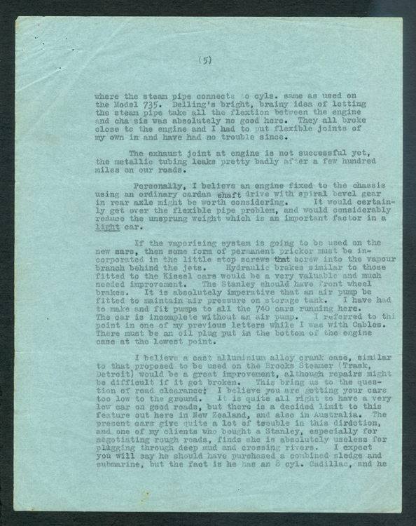
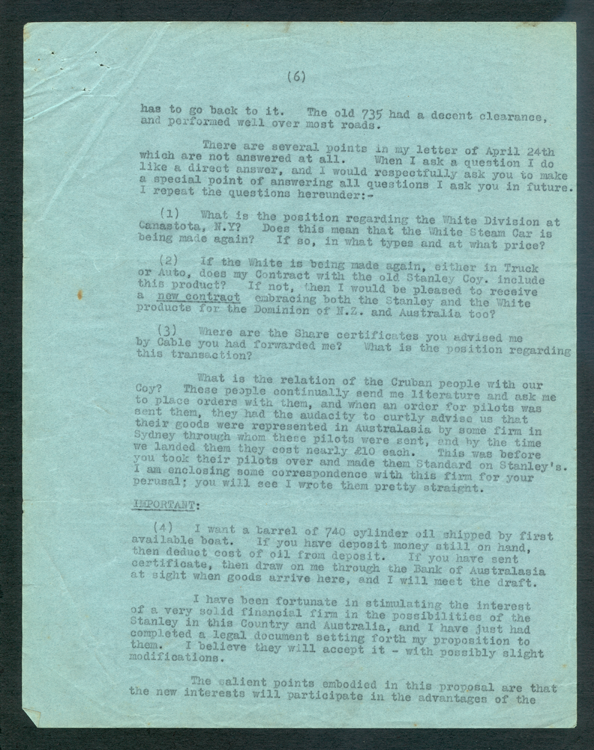
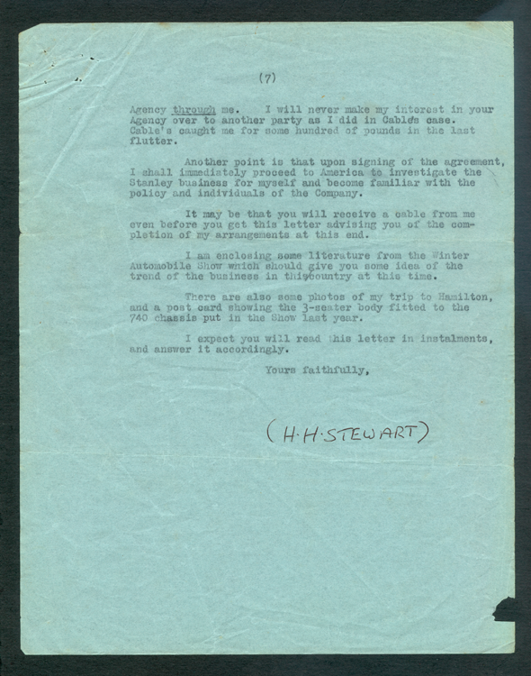
H. H. Stewart wrote to a Mr. Granlich on July 10, 1924 expressing his opinion on steam car design. This was prior to his coming to Newton, MA to work on the design of the SV 252. Source: Stewart Archive.
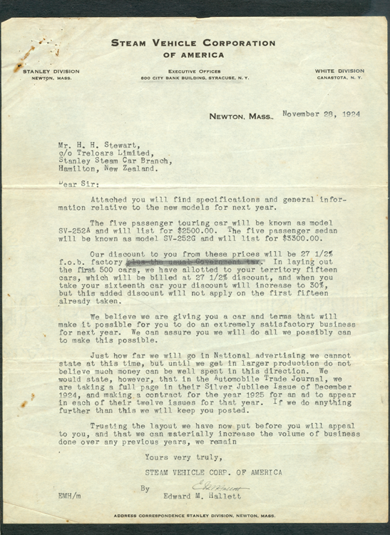
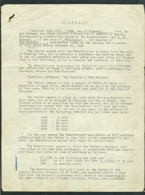
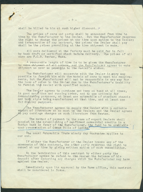
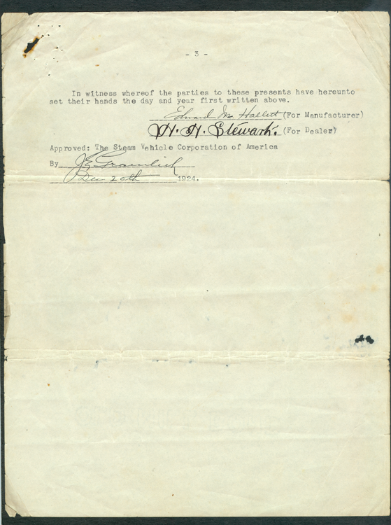
This is H. H. Stewart's contract with the Steam Vehicle Corporatin of America, dated November 28, 1924. The document is well worn and has notes written on the backs of several pages, suggesting that Stewart may have carried it in his pocket. Source: Stewart Archive.
The 1925 Stanley SV 252 Prototype.
Stewart traveled to Newton, MA in 1924 and helped to work on the prototype of the 1925 Model SV 252. During this time he took a series of snapshots of the prototype and the factory. He labeled some of these snapshots, particularly of the Sv 252 prototype.
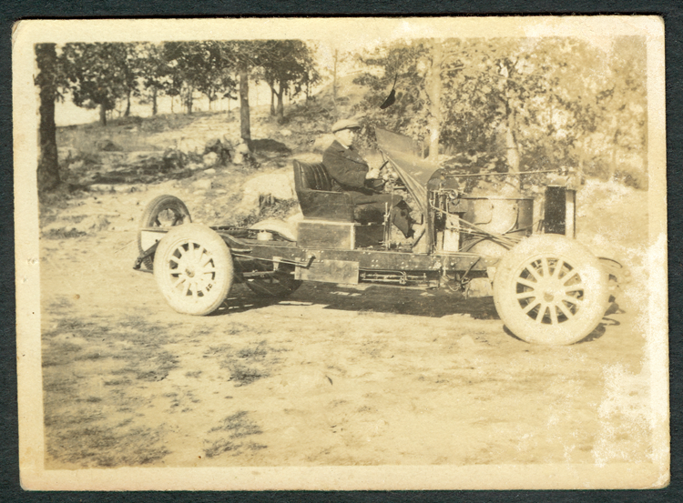
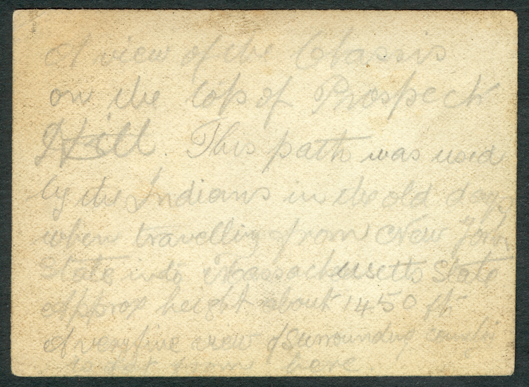
This is the left side view of the SV prototype. H. H. Stewart's notation on the back of the photo reads as follows: A view of the chassis on top of Prospect Hill. This path was used by the Indians in the old days when traveling from new York state into Massachusetts state. Approx. height about 1450 ft. A very fine view of surrounding countryside from here. Unfortunately, Stewart did not date the photograph or identify the person driving the car. The new SV type pumps and the SV pump pit are clearly visible. The front seat has been rigged for test driving the chassis and most certainly was from an earlier Stanley of some unknown model. Note the cowl protecting the driver and compare it with the chassis in Photo No. _____. The left side of the chassis should bear a maker's plate, but there is none. Clearly visible is the pilot fuel valve protruding through the frame and a light. Next to the light is the electric switch for heating the pilot and the electrical pilot lighting wand is clearly visible on the exterior of the frame, held in place by its bracket. Note the shape of the frame just to the right of the left rear wheel and notice how it sweeps up. The hydraulic brake line comes through the frame just prior to the upward sweep. The burner has been mounted to give access from the right side of the car and one can see the pilot protruding from the burner. The boiler water level automatic slopes toward the front and the boiler pressure automatic is visible against the firewall. There is a long bracket holding the firewall parallel. The boiler deserves special notice. Notice that the two lines emerging from the boiler do so well below the top of the smoke bonnet. The smoke bonnet is indeed a flat piece that is held to the boiler by six long machine screws that are welded to the boiler and protrude through the top of the smoke bonnet. The smoke is carried to the exhaust through an opening that is an integral part of the boiler exterior and is clearly visible here. This is identical to the boiler shell that is part of SV 25018 INSERT PHOTO HERE. The Johnson Bar is clearly visible beside the driver's right leg. There are no running board support brackets. The fuel pressure tank with its inflowing compressed air and its outflowing fuel is visible behind the seat.
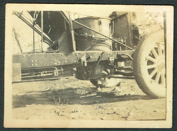
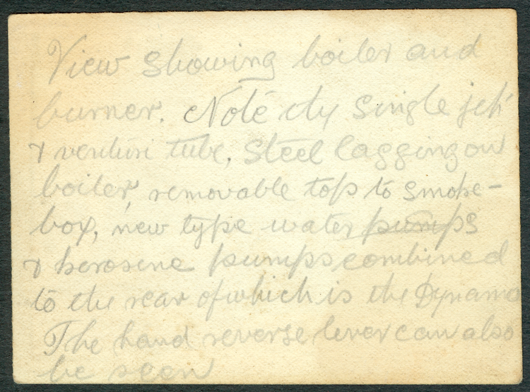
Stewart wrote the following on the back of this photo: "View showing boiler and burner. Note the single jet and Venturi tube, steel lagging on boiler, removable top to smoke box, new type water pumps combined to the rear of which is the dynamo. The hand reverse lever can also be seen." H Here he described many of the new features of the SV including its single venture burner and the easily removable smoke bonnet. Barely but clearly visible is the "u" shaped throttle control lever used on the SVs and some of the Model 750s? (CHECK THIS OUT!!!!? One can also make out the two brake pedals coming through the floor. They are partly obscured by a frame piece that supports the temporary cowl and dash board. Especially visible is the pilot fuel valve, the electrical light for the burner, the single venture burner, and the electrical wand to heat the pilot. Surprisingly, Stewart makes no mention of the Foxboro water level sending unit that is visible at the left front of the photograph. It is piped off the boiler feed water regulator. When this sending unit became filled with steam, it heated the sending unit and this registered on a gauge on the dash. Note again the openings in the side of the boiler wrapping below the top of the smoke bonnet and the flat smoke bonnet. There are two screws barely visible protruding from the top of the smoke bonnet. There were a total of six. The hydraulic line funning to the right front wheel is also visible.
Stewart wrote the following on the back of this photo: "View showing boiler and burner. Note the single jet and Venturi tube, steel lagging on boiler, removable top to smoke box, new type water pumps combined to the rear of which is the dynamo. The hand reverse lever can also be seen."
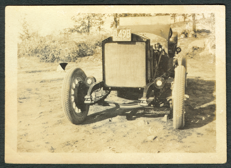
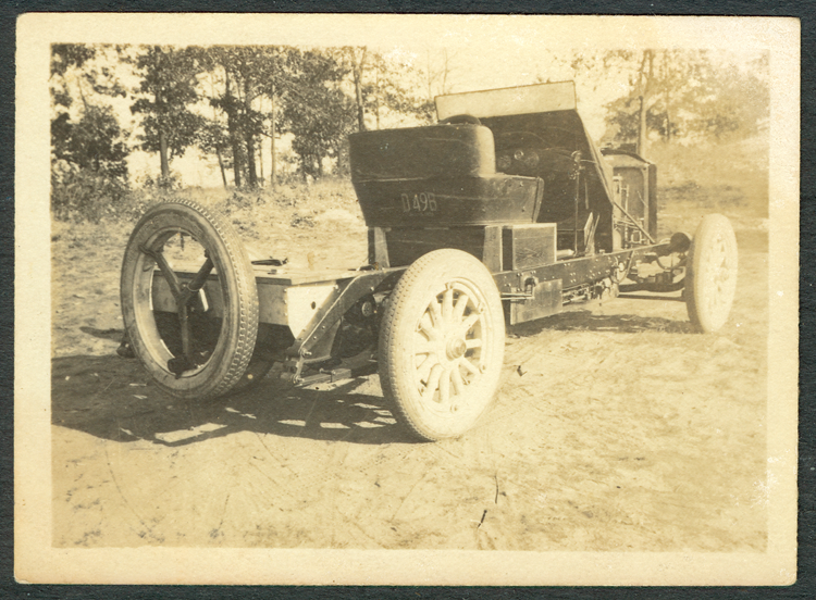
This photo shows the front of the prototype chassis on the top of Prospect hill. The Bosch shock absorbers are in clear view as are the Lockheed hydraulic brakes on the right front wheel. The sloping shape of the front axel is unusual and different than the front axels on surviving SV 252s. The license plate reads D, 49B MASS 1924. The Lockheed hydraulic fluid reservoir is sharply visible on the left side of the fire wall, where it was placed in the production SVs. While the condenser shape looks conventional and the two bolts holding it to the condenser are also found on SVs, the square design to the condenser itself does not appear on any standard SVs. To the left of the left rear wheel, the upward sweep of the frame is clearly visible. The front spring shackles are different than conventional SV shackles.
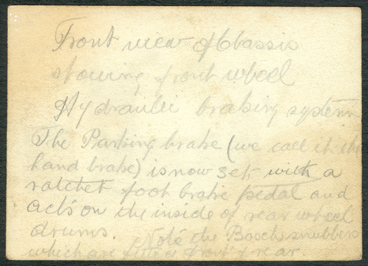
Stewart wrote the following on the back of this photo. "Front view of [the] chassis showing front wheel hydraulic braking system[.] The Parking brake (we call it the hand brake) is now set with a ratchet foot brake pedal and acts on the inside of [the] rear wheel drums. Note the Bosch Snubbers which are fitted on front and rear." In the final version of the SV, the Bosch Snubbers were only fit to the front of the car, not the rear.
The D, 49B MASS 1924 license plate is attached to the back of the seat. The spare tire carrier is identical to the late Model 705 cars and to SVs. Stewart's notice about the fuel tanks is well taken. This tank has two openings in the top that protrude through the back shelf of the car. Stewart redesigned this tank by moving the openings to the outer edges. The pilot fuel tank sits inside the main fuel tank and is filled from the right rear. The main fuel tank is filled from the left rear. Both tanks have Boston gauges on them (GET NAMES HERE). The Bosch snubber is clearly visible just under the frame and to the left of the right rear wheel. Exactly how it was attached is not clear, but it was bolted to the frame. The strap running to the spring or rear end is clearly visible. The temporary dash is also visible. One can clearly see the duplex gauge on the right and the boiler pressure gauge on the left. The smaller gauge might be the Foxboro water level gauge or the steam cylinder oil pressure gauge. The SV used the same gauge as the Model 740 and 750. (CHECK THIS OUT!!) The rear shackles on this chassis appear to be stamped, while the shackles on most SVs are forged steel. The DOT grease fittings are also in place. The steam cylinder oiler is visible inside and above the right frame rail just behind the fire wall. It appears to have a sloping cover over it.
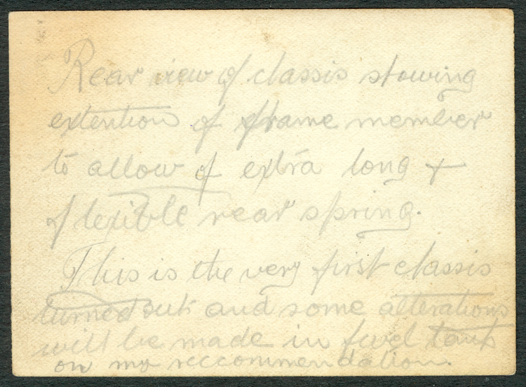
Stewart wrote on the back of this photo: Rear view of chassis showing extension of frame member to allow for extra long and flexible rear spring. This is the very first chassis turned out and some alterations will be made in fuel tank on my recommendations.
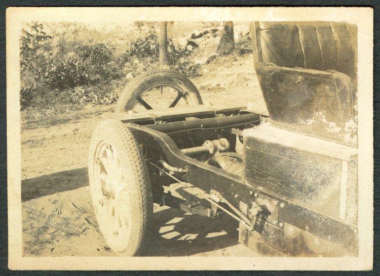
Of particular interest is the top of the rear end that shows the housing for the gear and shaft that run from the main rear end gear. This shaft then takes a right angle turn behind the generator and pumps before going through yet another ninety degree transition to change the rotary motion to reciprocating motion to run the pumps. A very convoluted way of getting motion to the pumps. Note the engine bolted into the rear end. This rounded engine casing is distinctly different than the rectangular engine case of the SV engine. The Bosch Snubbers are not visible in this photo, but what Stewart described as the "upward sweep of the chassis" is very clearly visible here, as are the caps to the fuel tank protruding through the shelf above the tank.
On the back of this photo, Stewart wrote "Another view of [the] rear end of [the] chassis showing brake rod for internal shoe brakes and flexible tube for contracting brakes (hydraulic) note the upward sweep of chassis and underslung springs."
The Stanley Factory - 1925.
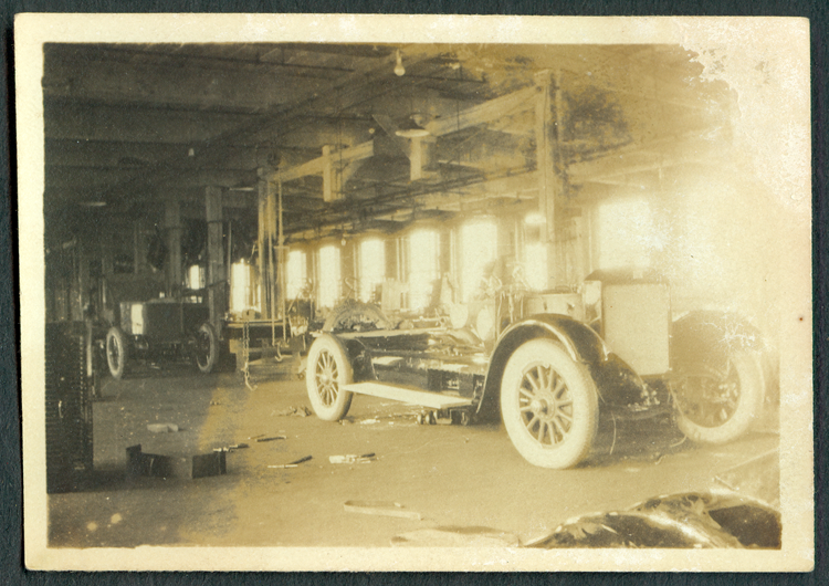
The chassis in the right foreground is clearly a 1925 SV chassis. Note the short running board and the shape of the left front fender. At the left rear, the curve in the frame clearly distinguishes this chassis from the Model 750 with its flat frame. The boiler is already in place as is the steam pressure regulator positioned on the left side of the firewall. The signature SV pump pit is clearly visible. Note what appears to be a dolly under the chassis in the foreground, suggesting that the assembly process had the engine on a dolly, rolled under the chassis, and lifted into place. Behind this chassis is a hand-operated chain fall apparently connected to a track attached to the ceiling. The chassis in the background may be the prototype SV 252. It appears to have a temporary canvas body extending up from the fire wall, as does the photo of the prototype at the top of ______. It too has its boiler installed.
This photograph apparently shows two SV bodies. Note the shape of the left front fender on the touring car body with the California top. This is clearly an SV fender and not a Model 750 fender, which sweeps nearly parallel to meet the running board. The body is fitted to a frame the front fender brackets are bolted to the frame suggesting that this is part of the "design" process. If the frames were purchased from an outside source, they would arrive without holes drilled for the various elements such as the brake lines, running board brackets, Johnson Bar brackets, etc. This would require fitting a body to the frame to locate holes for these elements. This may be what is happening in this photograph, as the frame has nothing attached to it. This is clearly not a final putting the body onto the frame step. There is a second body in the background on a dolly as is the body in the foreground. It is unclear if this is a touring body or a sedan body as the photo is taken directly from the front. Given the shape of the windshield, it appears to be another touring car. The back of the front seat is clearly visible through the cowl. Note the track along the ceiling.
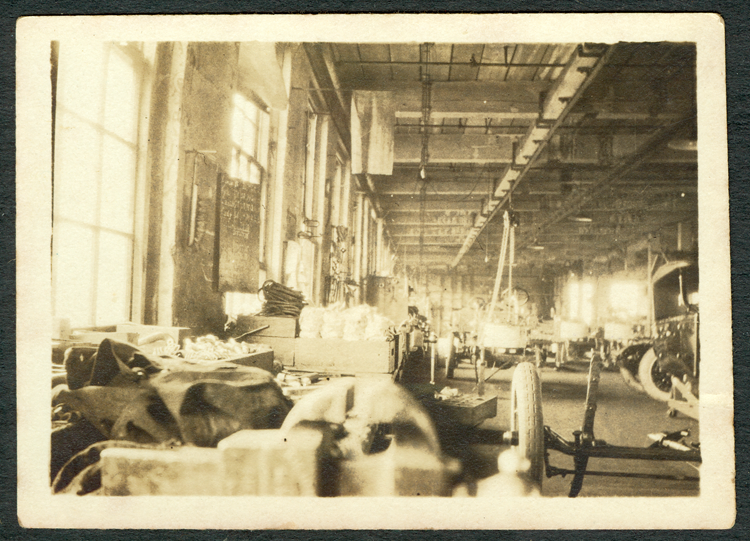
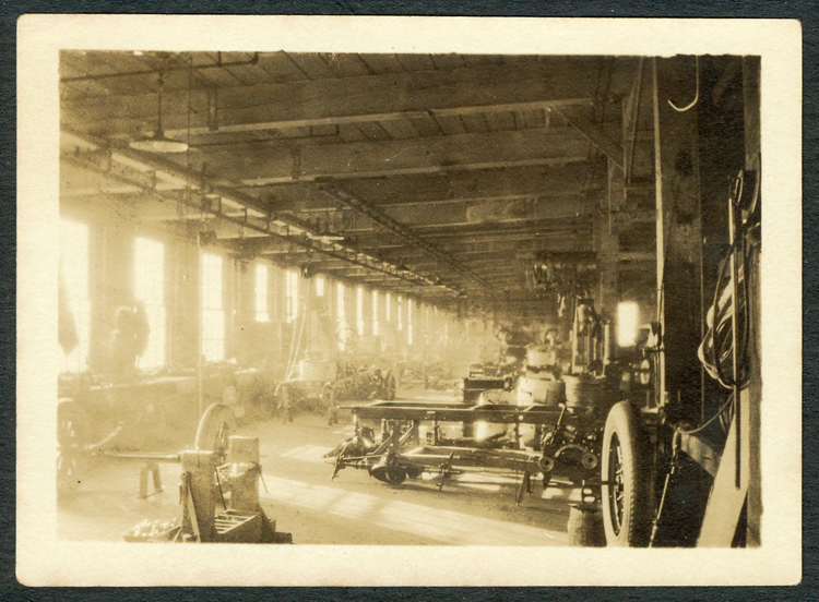
Inside the Stanley Factory in 1924. In the lower right forefront of the photo a front axel and tie rod are clearly seen with a leaf spring pointing into the air. To the right is a touring car body, probably a Model 750, as the support for the California top bows out. The SV 252A touring bodies were smaller and the windshield staction came straight up through the body. Notice that the touring car body is supported on a wooden dolly with castors. In the background, there is a partially completed chassis with a boiler in place. The boiler is directly beneath a hand-powered chain fall. Beside the brush on the left wall is a blackboard, but it is unreadable from this angle. Against the ceiling there appears to be a pair of tracks and the chain fall appears to be riding on the track to the left.
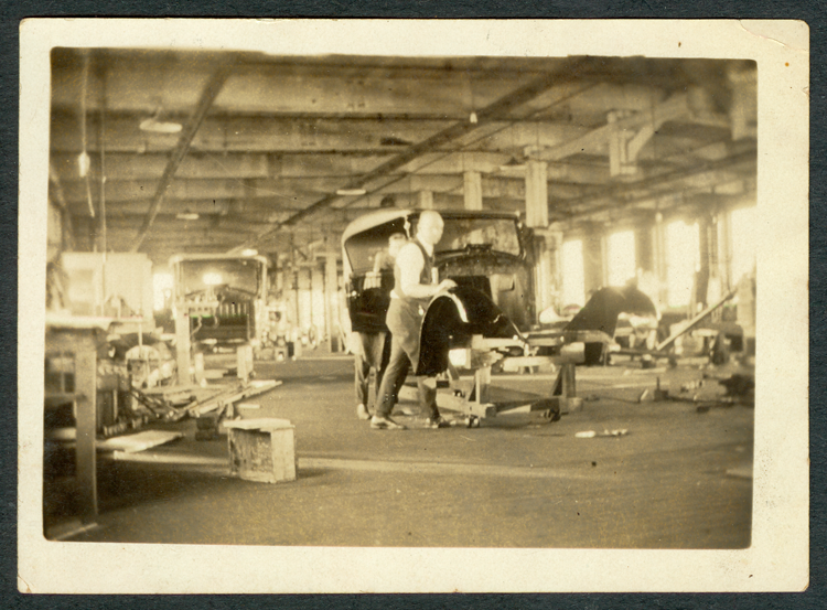
This workman appears to be assembling an SV chassis. Although it is difficult to tell from this angle, the chassis appears to have a hump towards the rear, suggesting it is an SV chassis. The pile of five frames on the floor to the left are almost certainly Model 750 chassis. They are flat across the top and do not have the hump towards the rear end as do the SV chassis. Furthermore there are body mounting brackets already attached to the sides of these chassis and SV bodies were bolted directly to the chassis and not to brackets mounted on the sides. The frames stacked behind them may be SV fames, as they appear to be curved at the far end. There are two Model 750 water tanks piled on top of the nine frames behind the five Model 750 frames. Just to the worker's right is the fire wall for this chassis and the steering column is clearly visible as well, although it does not have its steering wheel mounted yet. Note that the chassis is mounted on a heavy wooden dolly to facilitate its movement from place to place in the factory. The chassis is supported on large wooden blocks and a large piece of lumber runs under the rear of the frame extending over the sides of the dolly. There appears to be copper tubing on the left side of the frame and draped over the rear frame cross member.
At the right of this photograph is apparently the same front end shown in Photo No. ____. Note that the chassis in the center of the photograph is missing its front end and these parts are likely to come together soon. Notice the hand operated chain fall over the boiler and the track on the ceiling. Behind this chassis there appears to be still another chassis in the assembly process. To the right and behind what look like boilers stacked on top of each other, there are two steering wheels protruding into the air far enough apart to suggest they may be attached to two more chassis in the assembly process. This photograph was probably taken about fifteen or twenty feet to the right of Photograph No. ____. There is a rear end on the floor that may be a Model 750 rear end, as it has an oval recepticle for the engine, not the rectangular opening for the SV 252 engine. ath This photograph shows the same front
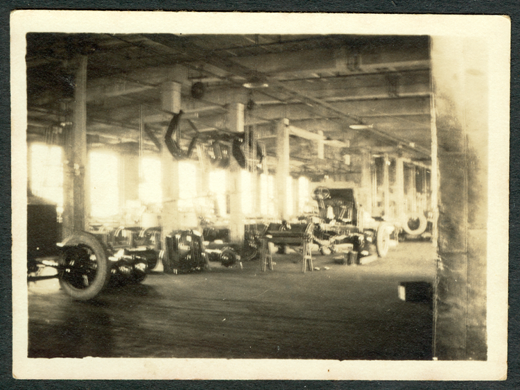
Sadly, this photograph is out of focus. It is unknown if H. H. Stewart moved when taking the photo or if the person who printed the negative did poor work. There is a chassis at the far left with what appears to be a condenser minus the condenser shell. There are several condenser shells leaning against a pillar to the right of the chassis. There is a nearly completed chassis with its engine and rear end removed. Its rear end is supported on a wooden tressell. It appears to have a sloping cowl similar to the prototype car and is almost certainly the car in the background of photo No. ___. At the far edge of the photo and partially obscured by a building pillar is another chassis, almost certainly the rear of the chassis in photo _____.
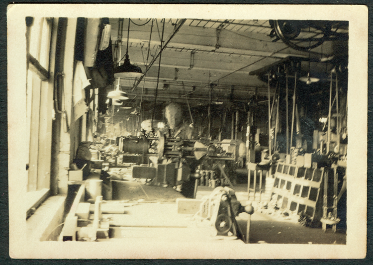
This workman is assembling what appears to be a Model 750 engine. It is held in a large vice mounted to the heavy workbench. At the right of the photograph is apparently a parts bin and leaning against it is an engine frame with an oval baffle, suggesting that it too is a Model 750 engine. The line shafting and countershaft drive what looks like a grinder to the left of the parts bin and perhaps an engine lathe behind the parts bin. One can see the different cone sizes on the headstock and the leg of the machine is just visible to the right of the engine frame leaning against the parts bin. There may be a pile of heads/blocks on the floor behind the workman. Look to the right of his vice and just below the engine crankshaft. Sadly, the workman moved during the taking of the photograph and his face is blurry.
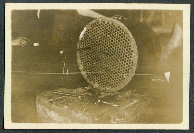
This photograph documents the boiler assembly process. The top nine and one half rows of holes have their steel tubes swedged. Note that there are no steel ferrules used here and the tubes are swedged directly into the top sheet. On the bench there is a hammer and a reamer. A swedge is protruding from the latest tube to be inserted. Note the handle protruding downward from the swedge. There is also a pile of rag waste on the bench, probably to wipe the excess cylinder oil from the swedge. Note the welding around the top sheet of the boiler. Stanley boilers were traditionally drawn in a huge press and only the top sheet needed to be welded into place. To the right of the photo is an exposed human leg with what may be a pair of shorts well above the knee. It seems unlikely that the worker's assistant would be so scantily dressed.
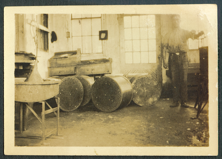
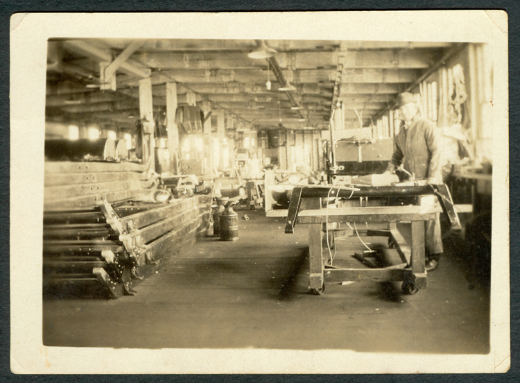
This is the Stanley's boiler testing department. The workman standing at the right has his hand on a series of pipes with a gauge protruding from the top of a boiler that is sitting on a stand of some sort. His hat hangs on the wall on the other side of the room. There are four boiler on the floor apparently awaiting testing. The stand at the left front of the picture appears to hold a burner pan. There appears to be an upside down funnel standing on the burner plate if indeed this is a burner.

